Materials Used
- Paper
- Cardboard (from cereal boxes, etc)
- Clear plastic
- Acrylic Paint
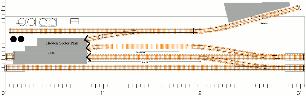
This module is based on ideas from the Small Layout Scrapbook, mainly by using the plan for Patagonia Yard and trying to make it fit with the T-Trak standard. By using a sector plate and transfer table in place of 5 regular switches I realized that I was limiting myself in the number of cars that can be switched at a time, but its an acceptable trade-off to keep the total cost down and make the module usable by itself, just like the original.
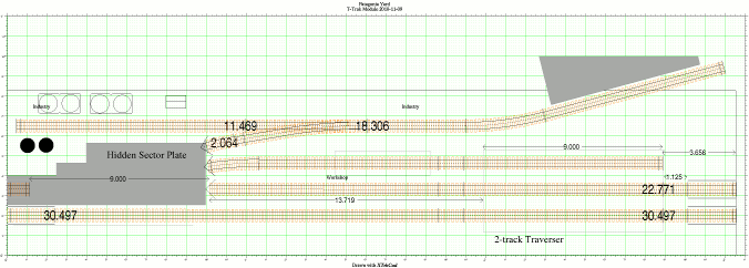
I was not completely satisfied with how the yard looked in the earlier plans and considered curving one of the industry sidings toward the back just to get away from having all the tracks parallel.
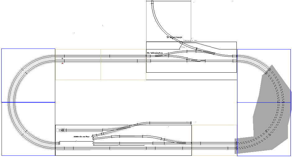
The diagram to the right will give you an idea how the switching module will integrate with the others to make a complete layout.
Sector Plate
Even before I had settled on a final track plan I began work on the sector plate. Originally I had planned on using a transfer table too (like the other layouts do). But when I made cardboard mock-ups for the double traverser and sector plate I discovered that the traverser was too complex and would not have been suitable on the main line. The sector plate looked like it would be manageable.
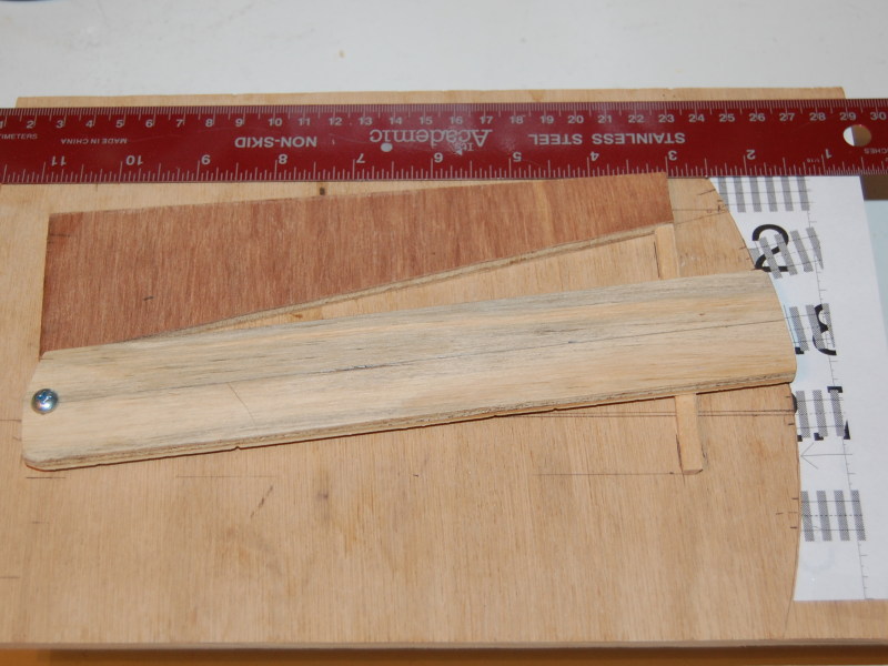
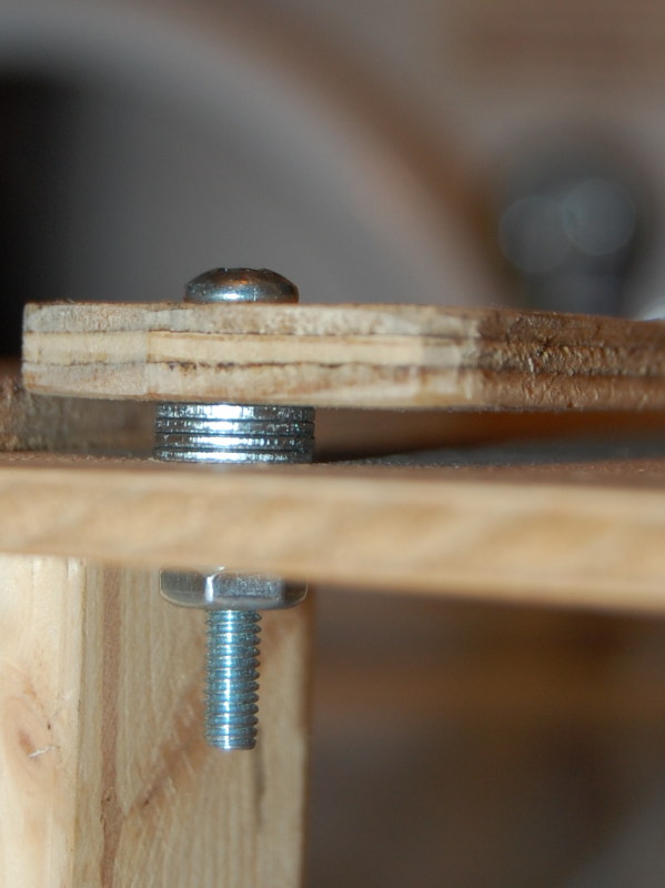
I built the real sector plate out of thin plywood as a single unit that could be attached to the rest of the module. I spent a long time trying to figure out a mechanical way to move it back and forth and finally came up with a lever that would be mounted on the front of the module. When the module box was constructed I cut a space for the sector plate and mounted it with some small bolts that I had on hand.
Track and Switches
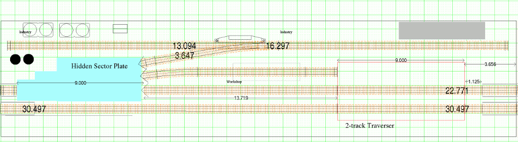
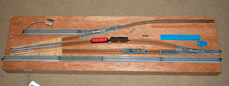
With the plate mounted, I could start marking where the tracks would go. The Xtrakcad printouts were very close and I only had to make slight adjustments to account for my own inaccuracy when mounting the sector plate.
During all this I attended the local annual train show and picked up some used Unitrack #6 switches. They weren't part the original plan of course, but it didn't take much to fit them in. I also got some more straight pieces to use for the mainline. The rest of the track I was planning on using 2 pieces of atlas code 80 flex, but nobody local carried it. The one LHS that specializes in radio control vehicles did say they had some code 55 flex so I decided to give it a shot. It turned out to be Peco and was more expensive than I wanted, but I went with it. At least I don't have to worry about changing wheels for now. ;-)
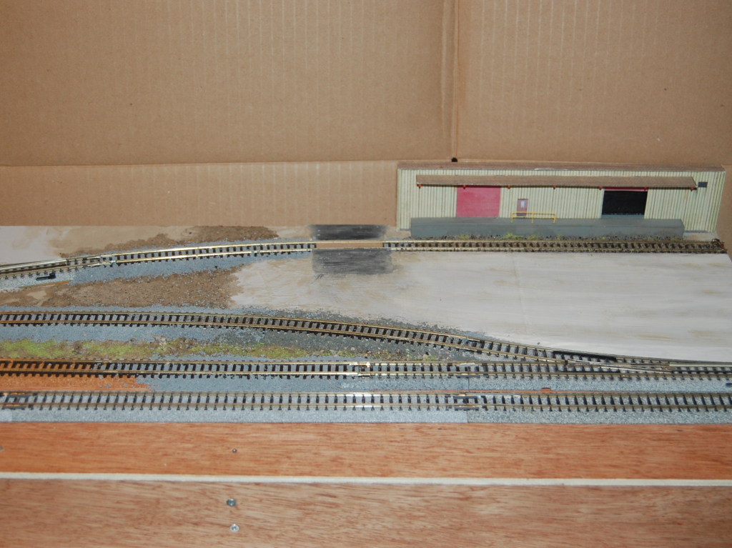
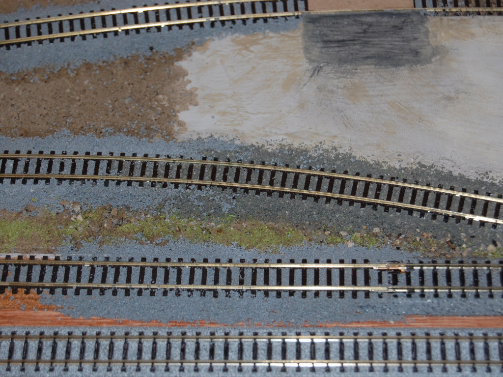
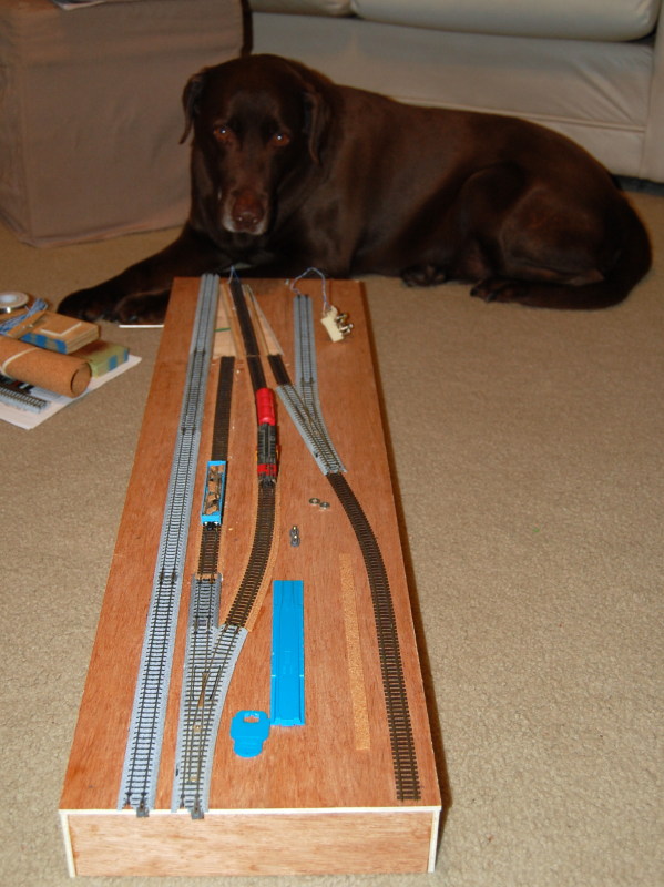
So after cutting and bending I have the tracks ready for feeders and joiners.
Structures
My original intent was to hide the sector plate and let it represent a series of switches further up the line. Unfortunately I discovered that hiding the sector plate area also hid too much of the left hand siding.
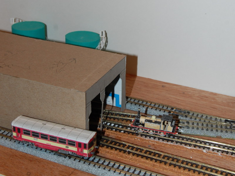
So then I began pondering ways to keep the area hidden, but let me see activity occurring behind it. Leaving it open was not an option since I didn't leave room to detail the tracks on the sector plate (such as on the Middletown layout), or to hide the wires beneath it. The next option was to hide portions using a wall and an overpass.
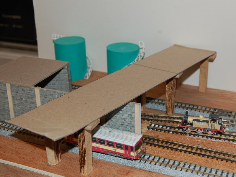
Eventually I settled on a wall design that includes an area for an elevated building which would cover one end of the sector plate, while a elevated highway blocks the view of the other end.
Industries
On the right side of the board is the building supplies spur. There is just enough room behind the track for a building flat that will have the loading dock. The loading dock is my interpretation of the actual LP Building Supplies outside Wilmington, NC.
I started by downloading some textures from CG Textures and importing them into Inkscape where I would draw the building outline, doors, and loading platform. At first I just drew it all as one image and after printing several drafts I separated the parts into different layers.
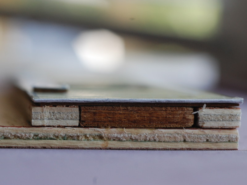
The first layer was then glued to a piece of cardboard and the door ways were cut out. Then I glued the doors into place and glued a second layer of cardboard behind the closed ones. Once I did a test fit though, I realized I had plenty of space and could use some plywood to fill the rest of the gap and give the building more strength. Also I would be able to make a deeper recess for the open door to make room for a small loading scene.
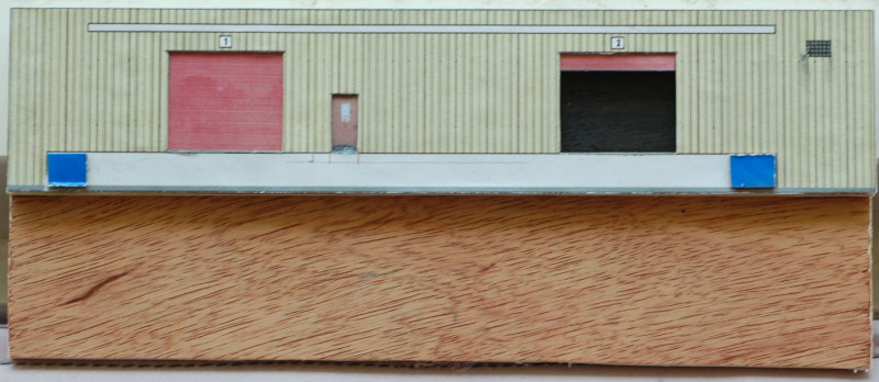
So I ended up with 4 layers (6 if you count the paper). The back piece of plywood extended down past the top of the module so I could attach it to the back later.
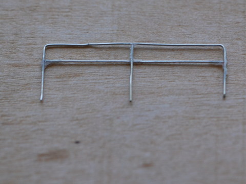
The next step was to build the loading dock that extends most of the width of this side of the building. After driving by the prototype I realized it had some sort of railing outside the smaller door. I tried to make something with 24-gauge floral wire and superglue. Close up it looks really rough, but mounted on the building it adds a nice touch.
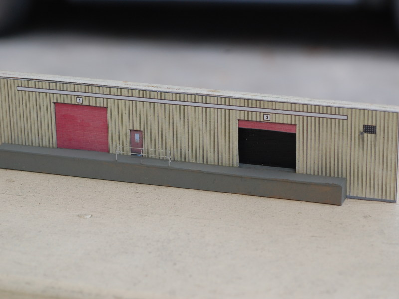
I had to make a couple more trips by the prototype to figure out what kind of roof was over the loading dock. I tried to replicate it as best as I could using cardboard and toothpicks.